Home> Technical Articles> Cross Roller Bearing Application Reference
- Address1589 Tampines Industrial Distributor Avenue 5 Singapore 528759
- Factory Address1589 Tampines Industrial Distributor Avenue 5 Singapore 528759
- Worktime9.00--18.00
- Phone(Working Time)0065-31591338
- Phone(Nonworking Time)0065-31591338
- Fax0065-31591338
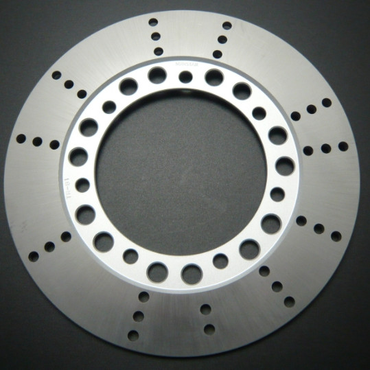
With the emergence of new technologies from German Industry 4.0, the machine tool manufacturing industry faces greater opportunities and challenges. How to achieve the best processing quality in the shortest time, thus improving the processing efficiency and reducing labor intensity is particularly important. The vertical lathe spindle assembly is one of the important components of the main drive. The machining accuracy of the machine tool is closely related to the structural performance of the main drive system. The spindle structure is the main load-bearing component of the machine tool and directly bears the cutting force, so the performance of the spindle component is very high. The requirements of all kinds of machine tools for their main transmission components are mainly the accuracy problem, that is, to ensure that the machine can drive the workpiece or tool to rotate accurately and stably around its axis under a certain load and speed, and keep this for a long time. A performance. The design and manufacture of the spindle components are all based on solving this basic problem. In order to meet the corresponding accuracy requirements, usually, the spindle assembly should achieve the following objectives: improve the rotation accuracy, enhance the stiffness, improve the vibration resistance, reduce the temperature rise and thermal deformation, and enhance the wear resistance. Therefore, the previous spindle structure has been designed to achieve these goals.
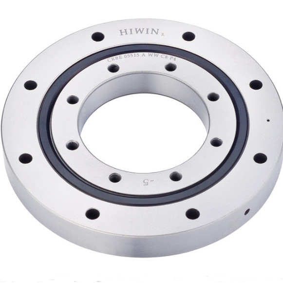
Most of the vertical lathes use the rolling bearing guide rail structure. In the main shaft part of the vertical lathe, the fixed short main shaft structure is generally adopted, and the high-precision double-row short cylindrical roller bearing is used in the radial direction. The bearing is mounted on the main shaft of the table. The taper of the hole is adjusted to ensure the rotation accuracy of the table by adjusting the radial gap. The high-precision thrust ball bearing is used as the rolling guide in the axial direction, and the preload is added in the axial direction. By adjusting the adjustment pad at the center of the spindle and adjusting the contact area between the central tapered hole of the radial bearing and the main shaft, the rotation precision of the table is improved. Carrying capacity. Therefore, the conventional spindle structure uses three sets of bearings, namely, centering bearings, guide rail bearings, and pre-tightening bearings. The cooperation between the main shaft and the centering bearing requires strict tolerance control, so the manufacturing process of the main shaft is relatively cumbersome and the precision requirements are relatively high. Secondly, the pre-tightening bearing is also relatively high in assembly requirements. If the pre-tightening force is too large, it will affect the service life of the bearing; if the pre-tightening force is too small, the accuracy of the spindle will be affected accordingly. How to solve the above difficulties, the optimization design of the spindle structure is a major upgrade. With the continuous development of technology, the spindle structure is constantly inspiring and innovating. Crossed roller bearings have many advantages such as small footprint, compact structure, convenient adjustment and maintenance. If cross-roller bearings are applied to the spindle structure, it will inevitably bring a new revolution to the vertical structure of the vertical car. Cross roller bearings are used in a wide range of applications, including precision rotary tables for machine tools, vertical lathes, horizontal lathes, vertical grinders, large hobbing machines, rotary bogies, industrial robots, etc. This section focuses on the study of crossed roller bearings. Application of the lathe spindle structure.
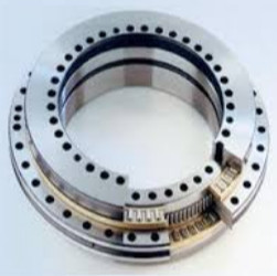
Crossed roller bearings have many advantages, such as high rotation accuracy, simplified operation and installation, high endurance, space saving, high speed capability, low moment of inertia, low torque, easy control of angular division, optimization of preload, stiffness, etc. . The figure below shows the application of a crossed roller bearing on the main shaft. The cross roller bearing has a simple structure, the middle part is a spindle encoder, and the worktable and the ring gear are carried on the crossed roller bearing. Compared with the previous spindle structure, the original three sets of bearings are simplified into a set of bearings, and the spindle structure and adjustment and installation are simpler. Adjustment step
The step is: remove the flange and the cover, then loosen the riser, take out the flange, remove the flange sleeve and the encoder, etc., then remove the workbench, unscrew the screw, and remove the upper part. Gland, remove the ring gear and crossed roller bearings, and tighten the bearing to the recommended value by grinding the adjustment pad. The parts are loaded in the reverse order of step one, that is, the adjustment is completed. It can be seen from the comparison method that the use of the cross roller bearing has the advantages of less occupied space and convenient adjustment and installation.
However, the cross roller bearing assembly should be relatively strict. In particular, the inner ring or outer ring of the crossed roller bearing is generally fixed by the bearing manufacturer with bolts and nuts. It can be directly installed in the bearing housing. The open bearing is easy to damage the internal structure, and at the same time, it has a great influence on the rotation performance and the force of the rolling element, so do not disassemble the bearing casually. Occasionally, the seams of the inner ring or the outer ring may be slightly deviated. Before installing the bearing housing, the bolts that fix the inner ring or the outer ring should be loosened and corrected by the plastic hammer before installation. When installing or disassembling, it is not necessary to apply an external force to the coupling bolt. Please pay attention to the dimensional tolerances of the installed components, so that the side compression flange can firmly press the inner ring or the outer ring from the side, so as to ensure the accuracy and performance of the cross roller bearing. The biggest feature of the crossed roller bearing is that its inner and outer rings are fixed with the cross roller collar after being installed in the roller and spacer cage to prevent separation from each other, so when installing the cross roller collar easy to use. Since the rollers are arranged in a cross arrangement, only one set of crossed roller collars can withstand loads in all directions, and the rigidity is increased by 3 to 4 times compared with the conventional model. At the same time, the crossed roller bearing has a two-part structure due to the inner ring or the outer ring of the crossed roller bearing, and the bearing clearance can be adjusted, and even if a preload is applied, a high-precision rotational motion can be obtained.
This structure fundamentally optimizes the spindle structure, solves the complexity of the vertical manufacturing, installation and maintenance of the vertical car, and improves the adjustment efficiency of the machine tool. Under the premise of ensuring high speed and high precision of the machine tool, the form of the spindle of this structure will be the future. The trend of machine tool spindles, this structure is rarely used in domestic machine tools, it is undoubtedly a major revolution, stable, reliable, superior performance of the spindle structure, but also the progress of the machinery industry.


 Best-selling Rexroth Vane Pumps
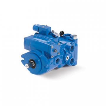 Best-selling Eaton-Vickers Piston Pumps
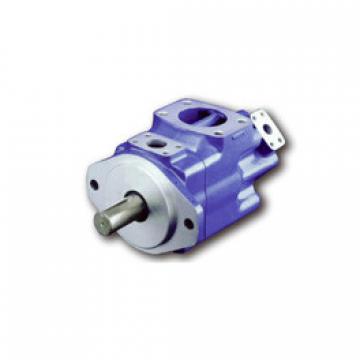 Best-selling Eaton-Vickers Vane Pumps
 Best-selling Eaton-Vickers Aluminum Gear Pumps
 Best- selling Parker’s GEAR PUMPS